There is a cognitive gap between the inside and outside of structural engineering.

For those who do not engage in structural engineering, it seems that as long as they can’t break and bend with their bare hands, they are all structures, so that infilled walls, pipes, aluminum alloy doors and windows…

Are all structures.

Those engaged in decoration call them “hard decoration”; In the view of structural people, they are “non structural members”.

Although people engaged in structure have a narrow understanding of structure, they like to call everything except “structure” in the narrow sense “non structure”; But when I first saw “reinforced concrete non structural wall” in Japanese literature more than ten years ago I still feel insulted for reinforced concrete: do you call reinforced concrete non structural?! yes, they do call some cast-in-situ reinforced concrete walls non structural members, and they have good reasons.

In short, all reinforced concrete walls do not have to meet the various checking calculation and structural requirements of shear walls in reinforced concrete specifications Concrete walls are all non structural walls.

They are not included in the bearing capacity checking calculation of the structure, but only as the bearing capacity reserve.

They have a variety of forms and a wide range of uses, They also have their own names that are easy to hear and remember and Chinese people have no reading difficulties (above).

Today’s story is a sad story about the square vertical wall.

1.

Before the RC infilled wall was just connected, the reinforced concrete (RC) square vertical wall was poured together with the RC Beams on the upper and lower sides, that is, the upper and lower ends were just connected.

However, people soon found that it had too little reinforcement (generally, the spacing between 150mm thick double-layer round 10 reinforcement and 300mm thick single-layer round 10 reinforcement in the outer wall and 120mm thick in the inner wall) is very rigid, which is particularly prone to brittle failure in earthquake.
As RC walls rigidly connected with the main structure, they could have provided a lot of bearing capacity reserves.
However, they broke down before the main structure of RC frame can fully display its ability, rattling and bearing capacity reserves No.
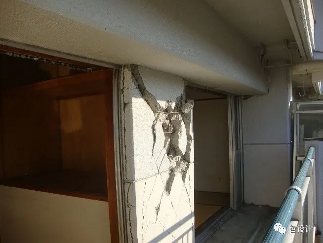
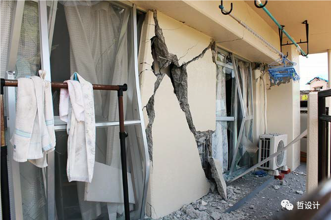
Such earthquake damage has occurred in several earthquakes in Japan in recent years.
For example, in the East Japan earthquake in 2011: in the Kumamoto earthquake in 2016: or in our experiment: 2.
Set up a jointed RC infilled wall, so someone came up with an idea.
Since these non structural walls do not participate in the checking calculation of structural bearing capacity and are so easy to break down in an earthquake, it is better to simply set a joint between them and the main structure to separate them from the main structure.
For example, as shown in the figure below: in this way, except for the force transmitted by the three limit bars, the wall limb will hardly be stressed, and of course it will not be damaged.
The experiment was so successful that it was not frightened at all.
As for why the joint is set at the bottom of the wall instead of the top of the wall, it is mainly for the convenience of construction.
These RC infilled walls are poured together with the main structure.
If you want to set a joint on the wall top, it will be difficult to construct.
3.
Jointed RC infilled wall + energy dissipator.
However, like another battlefield of the rigid and flexible struggle in Japan’s seismic circles in the last century, some people raised objections to the setting of joints in RC infilled wall: a good reinforced concrete wall, so considerable bearing capacity and safety reserve, how can we say no? I don’t respect you! So the little partner in Japan came up with a way: plug some energy dissipators in the joints and concentrate the deformation on the energy dissipators, which can maintain a certain bearing capacity on the one hand; On the other hand, it will not quit work prematurely because of brittle failure.
This idea, emmm, how to say, doesn’t really appeal to me.
But you might as well try it.
What if it’s fun? We think of two forms of arranging energy dissipators.
One is to continue the construction tradition of setting joints under the wall and arrange the energy dissipater in the bottom gap, which is called “bottom energy dissipation wall” for the time being; The other is to arrange the energy dissipater at the reverse bending point of the wall limb, that is, the middle of the wall limb, which is called “middle energy dissipation wall” for the time being.
We believe that both have their own advantages: the bottom energy dissipation wall takes care of the traditional joint construction technology; The stress of the middle energy dissipation wall is more reasonable.
But tests show that, Both have their own shortcomings (now we can start to be sad).
The cantilever of the bottom energy dissipation wall is long.
After the wall limb is cracked, its deformation accounts for a large proportion, and the role of the energy dissipation device is small.
Its failure is mainly concentrated in the root of the wall limb.
First, it is bent and yielded, then the concrete on both sides is crushed, the reinforcement is buckled, and finally the shear bearing capacity is directly lost.
The wall limb of the middle energy dissipation wall is relatively short, has high stiffness, and the wall limb There is no bending yield, so the proportion of wall limb bending is small; However, misfortunes and blessings depend on each other, and the damage of the middle energy dissipation wall is mainly manifested in the damage of the connection part of the energy dissipator.
When the inter story displacement angle is large in the later stage of the test, the energy dissipation device simply withdrew from work because of the connection failure.
In the bottom energy dissipation wall and the middle energy dissipation wall, the total shear force of the wall limb is similar, and the stud design of the connecting node is the same as that of the wall limb.
Why is the connecting node of the bottom energy dissipation wall OK, while the connecting node of the middle energy dissipation wall broken into slag? One conjecture is: precisely because the two RC walls of the middle energy dissipation wall have short legs and high stiffness, it provides greater rotation constraints for the energy dissipation.
On the one hand, it is certainly conducive to concentrating the deformation on the energy dissipation and improving the damping efficiency; But on the other hand, The connection node of the energy dissipator is also increased (i.e.
stud group).
However, at the beginning of the design, the checking calculation of the bearing capacity of the stud group under the coupling action of bending and shear was not considered, but only its shear bearing capacity was checked.
The final conical failure form of the energy dissipator connection of the middle energy dissipation wall also confirmed this conjecture.
It has to be said that this is a design error.
How sad.
However, it is still just a mistake A conjecture may explain all the reasons or only part of the reasons..


