The hoisting of prefabricated components is one of the important links in the construction of prefabricated buildings.
In the actual lifting process, the construction personnel shall reasonably select the lifting tools and arrange the lifting points according to the type of components and the lifting environment, so as to ensure the stability of component lifting and avoid the pulling out of the lifting nails or the cracking and damage of components due to excessive local stress.
Based on this, this paper takes the prefabricated bay window as an example, comprehensively considers the coincidence degree of the center of gravity of the component and the center of gravity of the sling and the stress state of the component, and analyzes the lifting point arrangement method of the special-shaped component, in order to achieve the purpose of ensuring the lifting safety of the special-shaped prefabricated component.
1.
The prefabricated component hanging nail system has a large self weight and a variety of prefabricated components.
The construction personnel often need to use special embedded hanging nails and supporting slings to carry out hoisting.
The construction personnel can select the appropriate hanging nail system according to different component types and hoisting environments.
Currently, the commonly used hanging nail systems include round head hanging nail system, thread hanging nail system and flat plate hanging nail system.
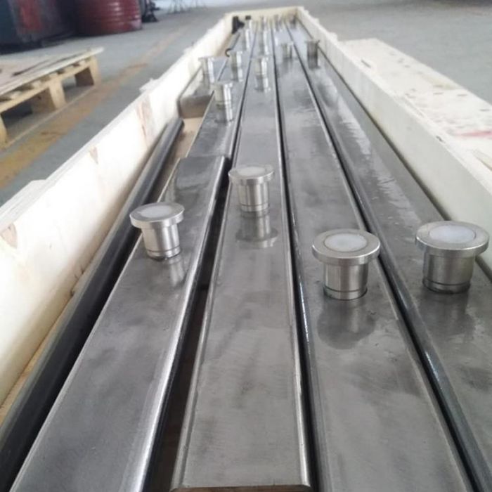
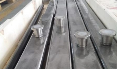
1.1 round head hanging nail system the round head hanging nail system includes round head hanging nails embedded in the components and duckbill buckles used to connect the slings.
Wherein the round head hanging nail is fixed on the concrete surface through a hemispherical socket; The lifting load is transmitted to the concrete by the circular fixed end anchor at the other end of the hanging nail, so as to realize the quick hooking.
1.2 thread hanging nail system the thread hanging nail system includes thread hanging nails and supporting external thread slings.
The installation and fixation of threaded hanging nails are relatively simple, and they can usually be directly anchored in the concrete without special grooves.
During hoisting, the construction personnel can screw the external thread sling into the hanging nail sleeve and anchor the anchor between the thread of the component and the concrete to improve the bearing capacity.
There are three common types of threaded hanging nail anchorage: steel bar straight anchor, steel bar bending anchor and steel plate end anchor.
1.3 plate hanging nail system plate hanging nail system includes plate hanging nails and special slings with rotating pins.
The plate hanging nail is composed of steel plates.
The bottom steel plate is anchored in the concrete and fixed by a flat spherical profiler.
At the same time, a groove is formed on the concrete surface.
The exposed steel plate is connected and fixed with the special lifting device with the rotating pin in the plate hanging nail system through the end hole.
During this process, the construction personnel shall rotate the pin to prevent the two from falling off.
2.
Layout principle of lifting points of prefabricated members: the lifting process of prefabricated members shall meet the provisions of the current national standard code for construction of concrete structures (gb50666-2011).
During the specific operation, the construction personnel shall also check the location, quantity and performance of embedded lifting parts of prefabricated members in combination with the actual construction conditions.
In addition, during the lifting of components, the staff shall ensure that the hook, sling and components of the lifting equipment are on the same vertical line, and ensure that the horizontal included angle between the sling and the components is not less than 45 °.
The lifting points of the laminated plate shall be symmetrically arranged to ensure the uniform stress of the laminated plate.
At this time, the construction personnel can use 4 lifting points, 6 lifting points or 8 lifting points for lifting.
It should be noted that the spacing of the lifting points perpendicular to the direction of the reinforcement truss should not be greater than the spacing of the lifting points parallel to the direction of the reinforcement truss.
3 Analysis of lifting point arrangement of prefabricated special-shaped members prefabricated special-shaped members refer to prefabricated concrete members with irregular shapes.
Different from regular members, the weight distribution of special-shaped members is not uniform.
If the construction personnel use the conventional method to arrange the lifting points during demoulding lifting and transportation lifting, it is likely that the center of gravity of the members and the center of gravity of the lifting tools will not be on the same vertical line, and then tilt.
In the specific installation process, once the inclination occurs, it will lead to a large error in the installation of components, and then cause the width of the splicing joint between adjacent components to increase, and the flatness and perpendicularity of components are difficult to achieve the expected effect.
Finally, it will seriously affect the accuracy of the alignment between the reinforcement and the grouting sleeve at the bottom of the component (see Fig.
1).
In order to avoid such problems, the construction personnel must scientifically arrange the embedded positions of the lifting points of the special-shaped precast concrete members, and at the same time determine the position of the center of gravity of the members, so as to ensure that the center of gravity of the lifting tools and the center of gravity of the members are on the same vertical line during the lifting process.
In the following, the arrangement of lifting points of prefabricated special-shaped members is analyzed by taking the prefabricated floating window commonly used in the project as an example.
3.1 calculation of gravity center position of prefabricated louver the prefabricated louver is a typical special-shaped prefabricated concrete component, which usually has the advantages of large lighting area and good ventilation effect.
However, due to the existence of the bay window, the gravity center of its component inevitably shifts to the side of the bay window.
The author analyzes and calculates the location of lifting points of special-shaped prefabricated concrete members by taking prefabricated louvers as an example (see Fig.
2 and Fig.
3).
The details are as follows.
In formula (1), X1 is the center of gravity coordinate of the whole wall in the front view of the louver, X2 is the center of gravity coordinate of the bay window in the front view of the louver, A1 is the total area of the wall in the front view of the louver, and A2 is the total area of the bay window in the front view of the louver.
In formula (2), Y1 is the sectional center of gravity coordinates of the entire wall in the louver section, Y2 is the upper center of gravity coordinates of the louver surface in the louver section, Y3 is the lower center of gravity coordinates of the louver surface in the louver section, A3 is the total area of the wall in the louver section, A4 is the total area of the upper louver surface in the louver section, and A4 is the total area of the lower louver surface in the louver section.
According to the calculation, when the center of gravity of the bay window is in the component, the construction personnel can adjust the position of the lifting point to make the center of gravity of the component and the center of gravity of the lifting appliance on the same vertical line during the lifting process; When the center of gravity of the bay window is outside the component, the construction personnel cannot adjust the lifting point position to achieve the purpose of stable lifting.
At this time, the construction personnel can fix the special adjustment device on the component and adjust the state of the component in combination with the chain block.
The hoisting can be carried out after the component is stable..


