✦✦ magnetic particle testing, as a common testing method in various standards and specifications, is widely used in the manufacturing and inspection of nuclear power, boiler, chemical pressure vessel and other equipment.

It is stipulated in tsg11-2020 boiler safety technology supervision regulation and tsg21-2016 fixed pressure vessel safety technology supervision regulation, Magnetic particle testing is preferred when magnetic particle testing can be performed.

Magnetic particle testing has incomparable advantages in the testing of ferritic materials, standard Nb / t47013 4-2015 nondestructive testing of pressure equipment Part 4: magnetic particle testing specifies the pole spacing, magnetization direction, magnetization times and magnetization time of magnetic yoke magnetic particle testing, and lists flat plate butt joints, plate-plate T-type fillet joints, pipe-plate fillet joints Yoke magnetization method of pipe pipe fillet joint and other structures.

There are more than these types of structures encountered in practical work.

Different structures have very different requirements for magnetic particle testing magnetization.

The relevant standards do not give the magnetization method of some special structures (such as weld bead interlayer weld, back gouging area of weld, weld repair area, groove and root of narrow gap weld, etc.), so we can only refer to the standards to select the appropriate testing equipment and testing specifications, and select the appropriate magnetization method according to the test verification.

The application of contact method is also limited by the workpiece structure.

Because it is easy to ignite and burn the workpiece, the contact method will be explicitly prohibited in some products.

Coil method and winding method are inconvenient in field testing.

Relatively speaking, yoke method is a magnetic particle testing method with flexible operation and convenient use in practical application.

1.

Workpiece structure and magnetic field distribution analysis for convenience of description, the geometric structure of flat butt joint is expressed as a type I structure, as shown in Figure 1; The structure of corner joint (including plate plate T-type corner joint, pipe plate corner joint and pipe pipe corner joint) is expressed as L-type structure, as shown in Figure 2; The special structures mentioned in this paper (such as narrow gap weld groove surface and root area) are expressed as U-shaped structure, as shown in Figure 3.

Figure 1 type I structure diagram 2L type structure diagram 3U type structure diagram ★ the characteristics of type I structure are: ① the magnetized area is in the same plane with the two magnetic poles; ② After the magnetic field enters the workpiece from the magnetic pole, it propagates along a straight line to the next magnetic pole.

The magnetic field path changes very little, and the magnetic field intensity decreases gradually with the increase of depth; ③ The magnetic pole is easy to fit with the workpiece surface, the magnetization operation is convenient and the process is simple.

The L-shaped structure is characterized by: ① the magnetization area is not in the same plane with the two magnetic poles, and the plane of the two magnetic poles is at an included angle of 90 °; ② After the magnetic field enters the workpiece from the magnetic pole, it bends and propagates to another magnetic pole along the surface of the workpiece.

The maximum bending angle is 90 °, and the magnetic field strength decreases gradually with the increase of depth; ③ The magnetic pole is not easy to fit the workpiece surface, especially the pipe butt joint.

Once the fitting is not good, it is difficult for the detection area to meet the magnetization requirements.

It is recommended to select the inclined contact magnetic pole.

The characteristics of U-shaped structure are: ① two magnetic poles are distributed on two independent surfaces, and their shortest connecting line is blocked by air medium.

The structure is similar to horseshoe magnet.

The structures on both sides of the magnetized area are perpendicular to the connecting line of the magnetic poles, and the bottom part of the magnetized area is parallel to the connecting line of the two magnetic poles; ② After the magnetic field enters the workpiece from the magnetic pole, it bends and propagates to another magnetic pole along the surface of the magnetized area.

The maximum bending angle is 180 °, and the magnetic field intensity decreases gradually with the increase of depth; ③ The magnetic pole is easy to fit the workpiece surface, which seems to be a simple magnetization operation, but the position of the magnetic pole will determine the magnetic field direction of the magnetized area and whether different magnetized areas can realize effective magnetization.

The depth of the U-shaped structure has a great impact on the length of the magnetic circuit.

If the magnetic circuit is too long, the area to be magnetized will not be effectively magnetized.

The sensitivity of magnetic particle testing is closely related to the magnetization direction.

If the defect direction is approximately parallel to the magnetization direction or the included angle with the workpiece surface is less than 20 °, it is difficult to be found.

Next, according to the special structure of Fig.

3, magnetic yoke magnetic particle testing is carried out to determine the influence of magnetic pole position, magnetic field trend, change of magnetic circuit length and other factors on the detection effect of magnetic particle testing, and determine the best magnetization process in combination with the theory of magnetic particle testing.

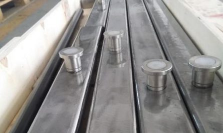
2 test verification and analysis 01 workpiece structure selection in order to improve the effectiveness of the verification test, the workpiece with deep U-shaped structure (narrow gap weld groove) is selected for the test, and its appearance is shown in Fig.
4.
The workpiece material is 15CrMoR, the plate thickness is 80mm, the maximum width of the upper part of the groove is 27mm, the width of the lower part of the groove is 18mm, and the groove depth is 60mm.
Fig.
4 selection of magnetization area for appearance 02 of workpiece with U-shaped structure in order to record the subsequent test, the workpiece is divided into 3 areas and the defects in 6 directions are determined, as shown in Fig.
5.
Area 1 in the figure is the left groove area, including defects ① parallel to the groove depth direction and defects ② perpendicular to the groove depth direction; Area 2 is the right groove area, including defects ③ parallel to the groove depth direction and defects ④ perpendicular to the groove depth direction; Area 3 is the bottom area, including defect ⑤ parallel to the bottom extension direction and defect ⑥ perpendicular to the bottom extension direction.
Fig.
5 magnetization area partition 03 test equipment the common variable pole spacing yoke is selected as the test equipment, and the models are CDX – Ⅲ and cy-1b; A1-30 / 100 sensitivity test piece and octagonal test block are selected for sensitivity verification.
04 test purpose: ① verify the relationship between magnetic pole position and magnetic field intensity in magnetized area; ② Verify the relationship between magnetic pole position and defect detection effect; ③ Verify the influence of the change of magnetic circuit path on the magnetization when the magnetic pole spacing is fixed and the relative position between the magnetic pole and the workpiece is different..


