Long press the QR code above to join the annual member of BIM blueprint! Obtain the project introduction and key and difficult points of the BIM technical documents of the project.

The design standard of the project is two-star green building.

The construction method is fabricated, and the structural form is shear wall / frame / fabricated.

The whole project consists of 12 main buildings, 3 supporting rooms and two underground parking garages, of which 5-18 floors are fabricated component floors.

[floors 5-18 are fabricated component floors] the project has large quantities, short construction period and complex pipeline layout.

It is the first large-scale concrete fabricated building in the province.

The fabricated components of the project include: laminated plates, prefabricated internal and external walls, prefabricated stairs, assembly parts, etc.

in order to fully display the project characteristics, overcome the project difficulties and ensure the construction quality, the owner requires the application of BIM Technology in the construction stage of each discipline, the owner A new set of BIM management mode jointly used by the supervisor and the construction party is indispensable.

The general contractor has two construction units.

The two construction units operate on the same platform, which is different from the previous management mode.

At the same time, it meets the requirements of the two construction units and has higher requirements for the platform.

00 assembly direction BIM application 01 joint review of construction drawings according to the design drawings, use BIM software to create various professional models of the project, carry out dynamic visual display of the design results, test the constructability of the design, visually check the drawing problems in the drawings such as contradictions, no data information and data errors, and finally issue the comprehensive analysis report of drawings to help the joint review of drawings and ensure that there are no omissions in the joint review of drawings.

11.

The three-dimensional field layout modeling reflects the layout of the construction site, tests the rationality of the layout of the construction site, reasonably arranges the temporary facilities, production and operation areas and large-scale equipment installation in a dynamic way, and finally analyzes and selects the best scheme to improve the construction efficiency and quality, so as to achieve green construction, energy conservation and emission reduction.

2 disclosure of 3D visual template this project uses BIM Technology to build 3D virtual template, build and improve construction process library and form standardized process flow, which not only facilitates the understanding of on-site technicians, but also strengthens the operation process of on-site workers and standardizes working methods, so as to improve construction level and cost control.

At the same time, on the premise of model guidance, it not only saves materials and space, but also can be reused.

3.

The construction progress simulation applies BIM Technology to simulate the project progress.

The BIM simulated construction plan is compared with the actual construction plan to find out the areas of difference between the plan and the actual situation, analyze the reasons for the difference, and use BIM to simulate the construction situation and schedule arrangement of next week, formulate weekly plan assessment and non-compliance solutions, eliminate the delay of construction period, and visually report the progress to the construction and supervision units.

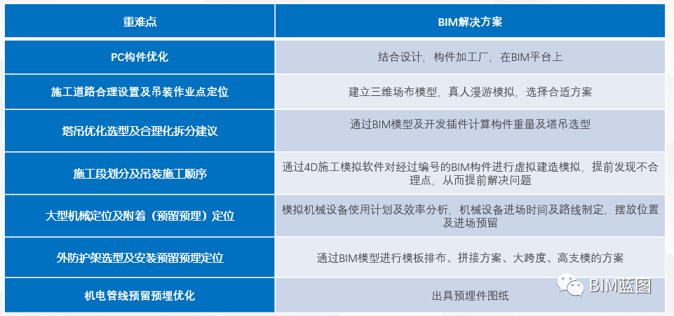
4 assembly construction process 5 key and difficult points and solutions of assembly construction 6pc component construction process split design is a technology integrating architectural scheme design, structural design, component manufacturing, construction and installation, procurement and supply of components and accessories.

The one-time split deepening of components is mainly aimed at component standardization, production and processing technology, finished product room design, hardbound points, switch and socket details; The secondary splitting of components is mainly used for the layout and selection of auxiliary tower cranes, which is convenient for on-site construction; 7pc components are split at one time, and the standardization of deep assembly building components has a vital impact on reducing the cost of the project.

There were 191 prefabricated components of 72 kinds in the original design.

After BIM design standardization, the types of prefabricated components were merged into 93 of 33 kinds.

Key analysis of secondary deepening (construction measures) of 8pc components: the project determines that the external protective frame adopts the standard external protective frame, the wall needs to be reserved and embedded, and the influencing factors such as stress reinforcement, inclined support embedded parts, embedded hanging nails, water and electricity reservation and embedding, split bolt holes and so on need to be considered.

BIM solution: use BIM Technology to assist the preparation of standard external protective frame scheme, establish a standard external protective frame model, accurately reflect the position relationship of stressed reinforcement, formwork split bolts, reserved holes for water and electricity, inclined support embedded parts and embedded hanging nails through the model, and determine the reservation and embedding of the final standard external protective frame on the prefabricated wallboard.
00bim other application 01 work quantity calculation uses Luban be to count the work quantity of BIM model, prepare work and materials by stages, and obtain the list details from BIM model.
The list items of each sub item are the same as the item code of national standard, including civil engineering, reinforcement, installation works, etc.
At the same time, the quantity calculation software is used to compare with the list of BIM model, provide the bill of quantities in stages according to the construction progress, and prepare materials in stages, so as to organize and guide the mobilization of materials required at the construction site.
02 pipeline comprehensively considers the clear height requirements of functional areas such as carriageway and parking space, finds out the areas where the clear height does not meet and puts forward solutions 03 earthwork calculation UAV take-off aerial survey data collection.
The photos taken are processed by the post flight software to generate the required mapping terrain.
And check the data to ensure the accuracy of the data.
The data results shall be imported into the graphic calculation software to generate the topographic surface and generate the required mapping, which shall include detailed elevation information.
Use the function of graphic calculation software to generate the original terrain, the current terrain, the terrain after the design is completed, and compare the difference between the terrain surfaces to obtain the earthwork.
By checking the transportation distance, ensure the minimum transportation distance of backfill, reduce the cost and reduce the construction time of earthwork stage.
04 3D scanning use 3D scanner to scan and sample components, generate solid model and compare with BIM model to assist component acceptance; The solid model generated by 3D scanning of reserved dowel bars in the transfer floor is compared with the BIM model to check the positioning deviation of dowel bars, and formulate corresponding treatment measures for different degrees of dimensional deviation..


