Steel structure single-layer plant engineering Chapter 1: components of steel structure single-layer plant I.

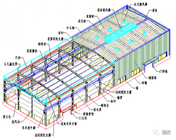
structural composition system of steel structure single-layer plant steel structure single-layer plant generally adopts the form of portal steel frame, and the structural system composition is shown in the following figure: Fig.

5-1-1.
Schematic diagram of steel structure plant 1 The foundation of steel structure single-layer powerhouse generally adopts independent foundation, manual hole digging pile foundation, rotary digging pile foundation, etc.
2.
Main structure steel structure the main structure of single storey plant includes: steel frame column, steel frame beam, crane beam, sandwich beam, etc.
The portal frame structure is mainly stressed by the transverse rigid frame composed of columns and beams.
The rigid frame is a plane stress system, and various loads are transmitted to the foundation through columns and beams.
Rigid frame columns and beams are generally made of equal section or variable section H-section steel.
3.
The secondary structure of single-layer workshop with secondary rigid structure steel structure includes: roof purlin and wall purlin.
Roof purlin and wall purlin bear the force transmitted from roof panel and wall panel and transmit the force to columns and beams.
Generally, C-section steel and Z-section steel are adopted.
4.
Support system the support system of steel structure single storey plant includes roof support, inter column support and tie rod support.
The steel structure single storey workshop is provided with column support and roof support, mainly to ensure the longitudinal stability of the structure.
According to the force form, the support is divided into rigid support and flexible support.
The rigid support is made of hot-rolled section steel, generally angle steel.
Round steel is generally used for flexible support.
The tie rod is a compressed circular steel pipe, which forms a stress closed system together with roof support and inter column support.
5.
Enclosure structure the maintenance structure of steel structure single storey plant includes: roof enclosure system and wall enclosure system.
6.
Auxiliary structure steel structure.
The auxiliary structure of single storey plant includes stairs, railings, canopy, etc.
2、 Basic form of portal steel frame 1 Typical portal steel frame a typical portal steel frame consists of steel frame columns and steel frame beams, which are connected by high-strength bolts.
Figure 5-1-2 schematic diagram of typical portal steel frame 2 The portal frame with crane is on the steel column of the typical portal steel frame, and the steel bracket is added.
The steel column of portal frame with crane can only use constant section H-section steel.
Figure 5-1-3 schematic diagram of portal frame with crane 3 Portal frame with local two floors.
Some single-layer steel structure plants should be considered as two floors locally to form the following portal steel frame with interlayer.
Figure 5-1-4 schematic diagram of portal frame with local second floor 4 Derived steel frame figure 5-1-5 schematic diagram of derived portal frame III.
load transfer process 1 Force transmission process of vertical load Fig.
5-1-6 force transmission process of vertical load Fig.
2 Force transmission process of horizontal load Fig.
5-1-7 schematic diagram of force transmission process of horizontal load IV.
determination of reasonable form of single-layer steel structure workshop 1 Selection of length and width} generally speaking, the principle that the length is greater than the width shall be followed when arranging the column grid, which can reduce the steel consumption of the rigid frame and the wind load of the support between columns, so as to reduce the steel consumption of the support system.
Example 1: if the building size is 60x50m, 60m should be taken as the length direction and 50m as the span direction when arranging the plant, that is, 60 (L) X50 (W), not 50 (L) X60 (W).
2 The technical and economic comparison of column spacing selection shows that the most economical column spacing under standard load is 8 ~ 9m.
When it exceeds 9m, the steel consumption of roof purlin and wall frame system increases too much, and the comprehensive cost is not economical.
Here, the standard load refers to the roof live load of 0.3kn/m2 and the basic wind pressure of 0.5kn/m2.
When the load is greater, the economic column spacing shall be reduced accordingly.
For the plant with more than 10 tons of traveling crane, the economic column spacing should be 6 ~ 7m.
When arranging the column spacing, if unequal column spacing is required, the column spacing of the end span shall be smaller than that of the middle span as far as possible, because the wind load of the end span is larger than that of the middle span.
In addition, when continuous purlin design is adopted, the deflection and mid span bending distance of the end span are always larger than those of other spans.
The use of smaller end span can make the design of roof purlin more convenient and economical.
Example 1: building length = 70m ﹐ economic column spacing can be taken: 1@7+7 @8+ 1@7 Or 1@8+6 @9+ 1@8 Example 2: building length = 130m, traveling 10 tons, economic column spacing can be taken: 1@5.5+17 @7+ 1@5.5 Or 20@6.5 3.
Determination of reasonable span} different production processes and use functions determine the plant span to a great extent.
Some projects even require light steel manufacturers to determine a more economic span according to their own use functions.
In order to meet the production process and use function as much as possible, a reasonable span shall be determined according to the height of the house.
Generally, when the column height and load are certain, the span shall be appropriately increased, and the increase of steel consumption of rigid frame is not obvious, but the space is saved, the foundation cost is low, and the comprehensive benefit is considerable.
Through a large number of calculations, it is found that when the eaves height is 6m, the column spacing is 7.5m and the load conditions are completely consistent, the unit steel consumption (q345-b) of rigid frame with span between 18-30m is 10-15kg / ㎡, when the steel consumption of rigid frame with span between 21-48m is 12-24kg / ㎡, when the eaves height is 12m and the span exceeds 48m, multi span rigid frame (swing column is set in the middle) should be used, Its steel consumption is more than 40% less than that of single span rigid frame.
Therefore, when designing portal rigid frame, a more economical span should be selected according to specific requirements, and it is not suitable to blindly pursue large span.
4.
The selection of roof slope is determined according to the comprehensive factors such as the structure of roof slab, the length of drainage slope and the height of column structure, generally 1 / 10 ~ 1 / 30.
The research shows that different roof slope has a great influence on the steel consumption of rigid frame..


