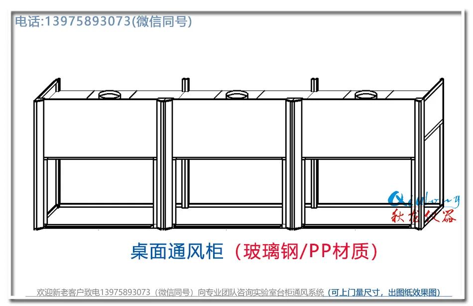
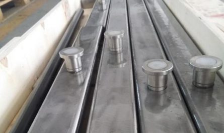
The ventilation duct (hereinafter referred to as the duct) is a channel for transporting dusty air flow.

It connects the dust hood, dust collector and fan into one and occupies an important position in the dust removal system.

Today, Qiulong instrument will share with you the components and accessories of the ventilation duct of the dust collector.

1、 Pipe component 1.

Elbow is a common component connecting pipes.

The resistance of elbow is related to the straight diameter D, radius of curvature R and the number of sections of elbow.

The larger the radius of curvature R, the smaller the resistance.

When 5D ~ 2 ° is taken as the design position of the elbow, it is usually not easy to reduce the resistance of the elbow from 1 ~ 2 ° in the design, but it will not be taken as too large from 5D ~ 2 ° in the elbow system.

2.

Tee in the dust removal system of gathering air network, the gas flow confluence component tee is often selected.

When the gas flow velocity of the two branch pipes in the confluence tee is different, it will produce ejection effect, accompanied by kinetic energy exchange, that is, those with high flow velocity lose kinetic energy, while those with low flow velocity gain kinetic energy, but the total kinetic energy is lost.

In order to reduce the resistance of the tee, the ejection condition should be prevented.

In the design, the gas flow velocity of the two branch pipes and the main pipe shall be the same as far as possible, that is, V1 = V2 = v3 Then the relationship between the two branch pipes and the straight section of the main pipe is D12 + D22 = D32 The resistance of the tee is related to the gas flow angle.

The included angle between the two branch pipes is usually 15 ° ~ 30 °, so as to ensure smooth gas flow and reduce the resistance loss.

Tee connection cannot be selected because the resistance of tee connection is 4 ~ 5 times greater than that of reasonable connection method.

In addition, avoid the use of cross as far as possible because the interference of gas flow in the cross is very large, which seriously affects the air suction effect and reduces the efficiency of the system.

3.

When the gas in the diffuser flows in the pipeline, if the section of the pipeline suddenly increases from small, the gas flow also increases sharply, resulting in obvious impact pressure loss.
In order to reduce the loss of resistance, smooth and excessive diffuser is usually selected.
The resistance of the diffuser is caused by the vortex zone formed by the gas flow before the inertia action increases when the section increases.
Angle of gradual expansion а The larger the eddy current area, the greater the kinetic energy loss.
When a exceeds 45 °, pressure loss is like impact loss.
In order to reduce the resistance of the diffuser, it is necessary to reduce the diffuser angle a as much as possible, but the smaller A is, the longer the diffuser is.
Generally, the angle of gradual expansion a should be 30 °.
4.
The interface between the pipe and the fan and the outlet fan produce mechanical vibration during operation.
In order to reduce the interference of mechanical vibration on the pipe, it is best to use a section of hose (such as canvas hose) at the position where the pipe is connected with the fan.
The straight pipe is usually selected at the outlet of the fan.
When it is necessary to assemble the elbow at the outlet of the fan due to the limitation of the assembly position, the rotation direction of the elbow shall be consistent with the rotation angle of the fan impeller.
The gas flow at the outlet of the pipeline is discharged into the air.
When the gas flow is discharged from the pipeline port, the kinetic energy of the gas flow before discharge will be lost.
In order to reduce the dynamic pressure loss at the outlet, the outlet can be made into a gradual expansion pipe with a small gradual expansion angle.
Try not to set a hood or other articles at the outlet.
At the same time, try to reduce the flow speed of exhaust air as much as possible.
2、 Pipe fitting 1.
Cleaning hole cleaning hole is generally set on the side of inclined and horizontal pipes, near or at the end of special-shaped pipes, tees and elbows.
The cleaning hole shall be made tightly without air leakage.
2.
The unbalanced resistance of the centralized dust removal system of the regulating valve is inevitable in operation.
Therefore, the regulating valve is set on the vertical pipe section connected with the dust suction hood.
Common regulating valves include butterfly valve, inclined gate valve, etc.
in general, straight gate valve is not allowed to be used on the pipeline in the suction section, because it is easy to cause pipeline blockage.
Used for regulating air volume.
Whether it is inclined insert plate or butterfly valve, it must be installed on the vertical pipe section.
Because strong vortices are generated before and after the valve plate, the dust is easy to deposit.
If this kind of valve plate is installed on the inclined pipe or horizontal pipe section, the deposited dust will also hinder the opening and closing of the valve plate or block the pipe.
3.
The dust removal system of measuring hole shall be started and adjusted before operation, and the aerodynamic performance shall also be measured during operation.
Therefore, the measuring hole for adjustment and test shall be reserved on the pipeline in advance.
The opening position of the measuring hole shall avoid the vortex area of the air flow as far as possible.
It is generally set on the pipe section connected with the dust suction cover: the pipe section before and after the dust collector; On the inlet and outlet pipe section of the fan; The dust collector shall be set at the position that can show the pressure loss of the equipment itself.
4.
The flange dust removal pipe is generally welded with steel plate and connected with flange plate to facilitate disassembly and cleaning.
The gasket in the flange plate can be rubber or thick paper pad soaked in water and boiled in dry oil and coated with lead oil.
Thick paper pad can be used for pipes transporting air with normal humidity not exceeding 70 ℃, and asbestos thick paper pad or asbestos rope can be used for pipes exceeding 70 ℃.
Qiulong instrument has been specialized in operating laboratory instruments and equipment for 27 years.
Welcome to inquire (18108442652)! Disclaimer: the content of this article comes from the Internet and the copyright belongs to the original author.
This content is prepared by Changsha Qiulong Instrument Equipment Co., Ltd.


