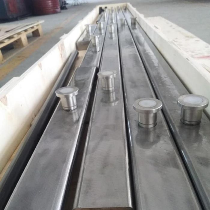
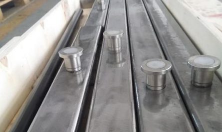
Interpret the technological process, key operation points and quality requirements of NPC component hoisting construction (NPC component – NewPrefabricated Concrete new concrete precast assembly technology) · NPC shear wall component hoisting construction technological process: wallboard hoisting in place → support → correction → support reinforcement → grout anchor pipe grouting → wallboard connection seam grouting prefabricated shear wall component hoisting construction technological process: 1.
The vertical component hoisting shall adopt slow lifting, fast lifting Slow release operation mode.
2.
A 20mm gap shall be kept between the bottom of vertical components and the floor to ensure the flow of grouting materials; The clearance shall be made of sizing blocks with different thicknesses of 1-10mm to ensure that the vertical components meet the design elevation after being installed in place.
3.
Before lifting the vertical components, check whether the rings in the embedded components are intact, the specification, model and location are correct, and the component is not more than 0.5m above the ground during the trial lifting.
The lifting speed shall be increased step by step and shall not be operated out of gear.
When the component is hoisted and lowered, the cable wind rope is tied at the root of the component to control the rotation of the component and ensure that the component is placed stably.
4.
When the component is about 1.5m away from the installation surface, it shall be adjusted slowly to the installation position; The reserved joint bars on the floor correspond to the reserved grouting pipes of the components one by one.
After all of them are accurately inserted into the grouting pipes, the components slowly descend; When the component is about 30cm away from the floor, the installation personnel shall assist in gently pushing the component or use a crowbar to preliminarily position it according to the positioning line; 5.
When the vertical components are in place, the vertical components shall be basically in place according to the axis, component sideline and measurement control line, and then the vertical component floor shall be temporarily fixed by using the adjustable inclined support upper and lower connecting plates through bolts and nuts, and the hook shall be removed after the vertical components are basically perpendicular to the floor.
6.
According to the plan division drawing and hoisting drawing of vertical components, the vertical components shall be hoisted in place one by one.
After the vertical components are in place, diagonal bracing shall be installed immediately.
Each vertical component shall be fixed with at least two diagonal bracing.
The diagonal bracing shall be installed on the same side of the vertical component.
The horizontal angle between the diagonal bracing and the floor shall not be less than 60 °.
1) Clean the pull bolts embedded on the ground, remove the plastic film wrapped on the surface and the splashed cement slurry, and expose the connection screw thread; Clean the sleeve on the component and install the screw.
Note that the screw shall not be screwed to the end, and the gap between the screw and the component surface is about 30mm; 2) Installation of diagonal support: cover the upper and lower base plates on the brace on the component and the bolts on the ground along the notch direction.
During installation, the base plate in one direction shall be sheathed on the screw, and then the brace shall be rotated to sheathe the base plate in the other direction on the screw; 3) Tighten the bolts on the components and the nuts of the ground embedded bolts.
At the same time, check whether the embedded sleeve in the component and the ground embedded bolt are loose.
If they are loose, they must be treated or replaced; 4) Rotate the diagonal brace to adjust the component to be initially vertical; Loosen the component hook and hoist the next component.
Use a guiding rule to measure the vertical deviation of the component, and pay attention to measuring at the side of the component; 7.
The verticality of vertical members shall be corrected by plumb bob or level ruler, and the middle steel pipe of adjustable diagonal support shall be rotated for fine adjustment until the vertical members are vertical; Use a 2m long guiding rule and feeler gauge to correct the flatness between vertical components to ensure that the wall axis and wall flatness meet the quality requirements, and the joints of the external wall tongue and groove joints are straight.
Quality requirements: allowable deviation (mm) of the project Inspection method Axis position 5 Steel ruler inspection Surface perpendicularity 5 Theodolite or suspension wire, steel ruler inspection Floor elevation ± 5 Level or guy wire, steel ruler inspection Member installation allowable deviation ± 5 Steel ruler inspection Prefabricated component external facing material damaged, should be repaired before installation, involving structural damage, should be negotiated by the design, construction and component processing units to meet the structural safety Use the function· Process flow of hoisting construction of NPC prefabricated composite beam: hoisting prefabricated composite beam in place → accurate correction of axis elevation → temporary fixation → support → unhooking operation process: 1.
Check the number, direction of prefabricated composite beam, appearance, specification, quantity, position, secondary beam opening position, etc.
of the lifting ring, select the steel beam carrying pole for hoisting, and the sling must correspond to the lifting ring on the prefabricated composite beam one by one.
2.
Before lifting the composite beam, the bottom elevation of the beam and the control line of the beam edge line shall be popped out on the calibrated wall with an ink line.
3.
Hoist the main beam first and then the secondary beam; The main beam must be calibrated before lifting the secondary beam.
4.
The shelving length of the composite beam is 15mm, and the shelving point uses 1~10mm sizing block.
When the prefabricated composite beam is in place, its axis control is in place at one time according to the control line; At the same time, adjust the beam bottom elevation through its lower independent support.
After the axis and elevation are correct, spot weld the main reinforcement of the prefabricated composite beam with the shear wall or beam reinforcement, and finally remove the sling.
5.
A precast composite beam requires at least two or more independent supports depending on the span size.
At the junction of the primary and secondary composite beams, the bottom formwork of the main beam and the independent support shall be in place at one time.
Quality requirements: 1.
When horizontal components are in place, temporary supports shall be installed immediately, and the height of temporary supports shall be adjusted according to the elevation and sideline control line to control the elevation of horizontal components.
2.
The distance between the temporary support and the support of the horizontal member shall not be greater than 500mm, and the distance between the temporary support and the horizontal member along the length direction shall not be greater than 2000mm; For laminated plates with a span of 4000 mm or more, temporary supports shall be added in the middle of the horizontal members for arching, and the arching height shall not be greater than 3 ‰ of the plate span· Process flow of hoisting construction of NPC prefabricated composite plates: hoisting the composite plates in place → supporting → correcting the elevation and shelving point length → supporting fixation and reinforcement → unhooking operation process: 1.
check the number of the composite plates, the position and quantity of the reserved holes, junction boxes, and the direction of the pointer for shelving the composite plates.
The operation mode of slow lifting, fast lifting and slow placing shall be adopted for the hoisting of laminated plate components..


