Summary: in order to realize the detection of cracks and holes in building wood components, a complete set of self-developed ultrasonic CT detection system is adopted, including non-metallic ultrasonic detector, weak signal amplification system, probe diameter conversion system, multi probe fixing system and ultrasonic CT analysis software.

Dry coupling technology is adopted in the detection without any coupling agent, which avoids the pollution of coupling agent to wooden cultural relics.
Through the test of laboratory standard test block, the test results consistent with the actual situation of the test block are obtained, and the wood components of ancient buildings in xiyuemiao, Shaanxi Province are tested on the spot, and good test results are obtained.
Keywords: Ultrasonic CT; Wood components; Defects # introduction Chinese ancient buildings are mainly brick and wood structures, and the overall gravity of ancient buildings is mainly decomposed and borne by wood components.
The wood defects of columns, girders and bucket arches in wood components have become the main factors seriously endangering the safety of ancient buildings.
In the health evaluation, protection and maintenance of ancient buildings, the evaluation of the preservation status of wood components is a very important issue.
The evaluation results will provide a basis for deciding what protection measures to take for the components.
There are many nondestructive testing technologies applied to wood defects, such as microwave technology, laser technology, X-ray technology, nuclear magnetic technology and stress wave technology based on sound and ultrasound.
Due to the influence of testing cost and field testing and other factors, microwave technology, laser technology, X-ray technology and nuclear magnetic technology have deficiencies in use; Ultrasonic testing technology is widely used because of its low detection cost and convenient on-site detection.
Chinese and foreign scholars use ultrasonic to detect wood, mainly taking the elastic modulus and speed of ultrasonic propagation in wood as the detection standard, and using ultrasonic head wave method to extract the time and speed of ultrasonic propagation in wood.
If the wood is defective, the propagation path of ultrasonic wave in it will change.
The acoustic signal first received by the receiving probe is the ultrasonic wave front signal first arrived at a point on the probe contact plane, forming the first wave signal received by the ultrasonic instrument.
The subsequent wave will be superimposed with the wave train arriving earlier to generate the superimposed signal, which contains various information inside the wood.
Due to the complexity of the formation of the follow-up wave, the analysis of the follow-up wave is very complex, which is the reason why the time and amplitude of the first wave are the primary criteria in the analysis of ultrasonic testing.
In the past, ultrasonic testing of wood was mostly carried out by a single transmission method.
The author has developed a set of ultrasonic CT system that can be used for the detection of ancient wood components, including ius2011punditlab + non-metallic ultrasonic detector, signal amplification and multi-channel control box, transducer diameter conversion device, multi transducer fixing device and ultrasonic CT analysis software.
Sonotecl4054khz longitudinal wave transducer is adopted as the transducer, and the analysis software is the ultrasonic CT analysis software developed by our research group.
Dry coupling technology is adopted in the detection without any coupling agent, which avoids the pollution of coupling agent to wooden cultural relics.
Through the test of laboratory standard test block, the test results consistent with the actual situation of the test block are obtained, and the wood components of ancient buildings in xiyuemiao, Shaanxi Province are tested on the spot, and good test results are obtained.
1 principle of ultrasonic CT detection the principle of ultrasonic CT detection has been described in many literatures, which is briefly introduced here.
In ultrasonic CT detection, two, three, four transmission and combined transmission methods are mostly used (Fig.
1).
A total of N rays are measured in the imaging profile.
Firstly, the profile is divided into m units (grids) according to the test accuracy.
The imaging method based on ray theory is reduced to solving the following equation: where Lij is the path length of the i-th ray in the j-th unit; SJ = 1 / VJ is the slowness value of the j-th unit; Ti is the travel time of the i-th ray.
By solving this matrix equation, the slowness value of each internal point can be obtained, and its reciprocal is the ultrasonic velocity of the corresponding point.
Calculate the ultrasonic velocity value of each pixel, reasonably divide the display color of each wave velocity segment, and display it on the imaging result diagram.
Fig.
1 ultrasonic CT detection system Fig.
1 ultrasonic CT detection system of ultrasonicct2 ultrasonic CT Detection System 2.1 transducer diameter conversion device in ultrasonic CT detection, measurement errors are often introduced due to inaccurate coordinates of detection points, resulting in error of analytical results.
At the same time, the directivity of ultrasonic is closely related to the half diffusion angle of ultrasonic transducer.
The smaller the half diffusion angle of transducer, the better the directivity.
The half diffusion angle of the transducer is inversely proportional to the diameter of the probe.
Too large contact area between transducer and wood surface will also introduce detection error.
The conical transducer with high cost can be used to solve this problem.
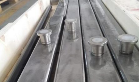
The diameter of the transducer is 50mm, so a conversion device is designed to convert the contact point to 10mm in diameter.
2.2 in the penetration ultrasonic testing of multi transducer fixing device, basically two transducers are used, one transmitting and one receiving, and the transducer is pressed on the surface of the tested object manually.
In the testing, it is necessary to apply liquid or colloidal coupling agent between the transducer and the tested object.
The author developed a multi transducer fixing device, which uses two nylon strap clips to fix up to 20 transducers on the measured section (Fig.
2).
Spiral connection is adopted between the transducer diameter replacement device and each transducer fixing block, which can ensure the effective contact between the transducer and the uneven measured section.
At the same time, the pressure generated by tightening the strap clamp will effectively compress the transducer with the measured surface, which not only solves the problem of manually compressing the transducer, but also realizes dry coupling detection, so as to avoid introducing unknown man-made pollution to wooden cultural relics.
Fig.
2 multi transducer fixing device Fig.
2multi sensorfixingapparatus 2.3 signal amplification and multi-channel control box adopt dry coupling technology, which inevitably reduces the amplitude of the received signal..


