The calculation of transmission line tower is generally based on truss system, and the members are two force bars hinged at both ends, that is, the axial force bearing members that can only bear tensile pressure.

The program calculates the internal force and bearing capacity based on this basic assumption.

But in fact, the pole connection of transmission line iron tower is bolt connection.

When the angle steel is connected on one side, the force transfer surface and the centroid of the angle steel will inevitably be eccentric.

In addition, when the two ends of the component are one bolt, the connection is close to the ideal hinge, but when there are multiple bolts, the performance of the end connection is actually between hinge and rigid connection, which belongs to semi-rigid connection.

The existence of end eccentricity and restraint will affect the compression stability bearing capacity of members.
The specification takes into account the corresponding correction coefficient to correct the slenderness ratio.
Based on this, this paper analyzes and discusses.
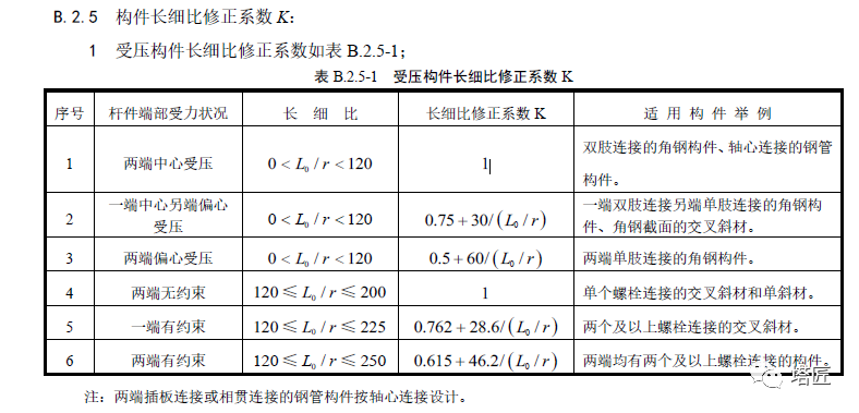
Relevant provisions of 15486-2020 industrial standard the provisions of 5486-2020 industrial standard on the slenderness ratio correction factor K of axial compression members are as follows.
It can be seen from the provisions of the specification that when the slenderness ratio l0/r is less than 120, the eccentricity of the slenderness ratio is corrected according to the eccentricity of both ends of the member.
(1) When the center of both ends is under pressure, because it is consistent with the calculation assumption, it is not corrected, and the correction factor is 1; (2) When the center of one end is eccentrically compressed, the correction factor is greater than 1; (3) When both ends are eccentrically compressed, the correction factor is greater than 1, and its value is greater than the case (2).
It can be seen from the provisions of the specification that when the slenderness ratio l0/r is not less than 120, the specification will restrict and correct the slenderness ratio in three cases according to the constraints at both ends of the member.
(1) When there is no constraint at both ends (single bolt), because it is consistent with the calculation assumption, it is not corrected, and the correction factor is 1; (2) When one end is restrained (two or more bolts), the correction factor is less than 1; (3) When there are constraints at both ends (two or more bolts), the correction factor is less than 1, and its value is less than the case (2).
The specification believes that the end eccentricity mainly affects the small slenderness ratio rod (short thick rod), and the end constraint mainly affects the large slenderness ratio rod (slender rod).
The slenderness ratio limit for eccentricity and constraint correction is 120.
2 relevant provisions of asce/sei10-15 American Standard the provisions of asce/sei10-15 American Standard on the slenderness ratio correction coefficient K of axial compression members are as follows.
It can be seen that for the slenderness ratio correction factor K of axial compression members, the provisions of the Chinese and American standards are completely consistent.
3 theoretical basis of steel structure stability the theoretical basis of end eccentricity and end constraint correction is steel structure stability theory.
Please refer to Professor Chen Ji’s stability theory and design of steel structures (5th Edition).
Now some chapters are intercepted as follows: 4 Calculation of eccentric correction coefficient K of slenderness ratio of axial compression members.
For the convenience of calculation and comparison, this paper records the correction coefficient of eccentric compression at the center of one end and the other end as PK1, and the correction coefficient of eccentric compression at both ends as PK2.
During calculation, the slenderness ratio l0/r before correction is taken as 0-120.
From the numerical point of view, the values of PK1 and PK2 are not less than 1, that is, multiply the slenderness ratio before correction by an amplification factor to reflect the reduction effect of the eccentric end of the member on the stable bearing capacity under compression.
The following is the calculation process of PK1 and PK2 eccentric correction coefficients.
In order to better explain its influence degree, the data are drawn into a curve.
In order to better calibrate the curve, when drawing the curve, set l0/r between 20-120, and the curve is as follows.
It can be seen from the above curve that the eccentric correction curve decreases with the decrease of the slenderness ratio l0/r before correction, and PK2 is always greater than PK1, which is equal to 1 when l0/r=120.
In order to better explain the influence degree of eccentricity at both ends, the data of pk2/pk1 are plotted as follows.
The following curve shows that the influence of eccentricity at both ends is greater than that at one end, and its degree of influence decreases with the decrease of l0/r.
5 calculation of the slenderness ratio constraint correction coefficient K of axial compression members for the convenience of calculation and comparison, this paper records the correction coefficient with constraints at one end as YK1 and the correction coefficient with constraints at both ends as YK2.
During calculation, the slenderness ratio l0/r before correction ranges from 120 to 250.
From the numerical point of view, the values of YK1 and YK2 are both less than 1, that is, multiply the slenderness ratio before correction by a reduction factor to reflect the effect of the end constraint of the member on the improvement of the compression stability bearing capacity.
The following is the calculation process of YK1 and YK2 constraint correction coefficients.
In order to better explain the degree of influence, the data are drawn into a curve.
It can be seen from the above curve that the constraint correction curve decreases with the decrease of the slenderness ratio l0/r before correction, and YK2 is always less than YK1, which is equal to 1 when l0/r=120.
In order to better explain the influence degree of constraints at both ends, draw the data of yk2/yk1 into a curve as follows.
The following curve shows that the influence of two end constraints is greater than that of one end constraints, and its influence increases with the decrease of l0/r.
6.
Software input method and precautions the above analysis are the requirements of the specification.
For the tower calculation, it is necessary to input the software accurately according to the input rules of the software and the specific structure of the rod end, otherwise it will cause calculation errors.
(1) Software input rules take smarttower software as an example, and column m is the input of end eccentricity and constraints, so as to realize the correction of slenderness ratio.
So how to identify the eccentricity and constraints at the end of the rod and input them into the software accurately.
This requires the designer to be fully familiar with the end structure of the member..


