1.

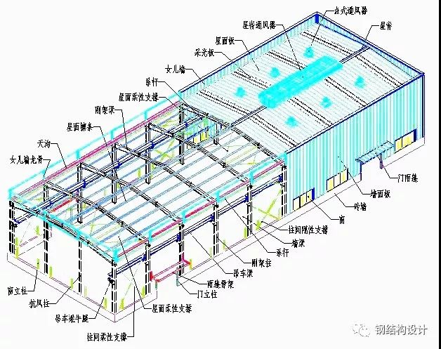
Building system 1-1, portal rigid frame system 1-1-1, basic component diagram 1-1-2, mechanical principle of portal rigid frame structure, which is a horizontal rigid frame composed of columns and beams, is the main force bearing structure, and the rigid frame is a plane force bearing system.

To ensure longitudinal stability, support between columns and roof support are set up.
The columns and beams of the rigid frame are made of H-section steel, and various loads are transmitted to the foundation through the columns and beams.
The support and tie rod rigid support are made of hot-rolled steel, usually angle steel.
The flexible support is made of round steel.
The tie bar is a compressed round steel pipe, which forms a stressed closed system with the support.
Roof purlins and wall beams are generally made of C-shaped steel or Z-shaped steel.
Bear the force transmitted from the roof panel and wall panel, and transfer this force to the columns and beams.
1-3.
Basic form of portal frame: a.
Typical portal frame: b.
Portal frame with crane: c.
Portal frame with local second floor: 1-1-4.
Basic nodes: a.
Column foot nodes: b.
Beam and column nodes: ■ Local second floor nodes refer to the multi-layer frame system.
1-1-5.
Derived form of rigid frame: Cranes and local second floors can be arranged in the derived form of rigid frame.
The essence of the gable rigid frame is also a multi span rigid frame, but the middle column rotates 90 degrees compared to the cross-section of the rigid frame column.
1-2.
Multi story frame system 1-2-1.
Frame diagram 1-2-2.
Explanation of mechanical model a.
Pure rigid frame: a frame with rigid connections in both vertical and horizontal directions.
b.
Rigid connection – support frame: adopt rigid connection horizontally, hinge joint vertically, and set support vertically to transmit horizontal force.
c.
Supporting frame: Hinged joints are used in both vertical and horizontal directions, and supports are set in both directions to transmit horizontal force.
d.
Sometimes, to ensure sufficient stiffness, supports are also installed in rigid frames.
Frame columns can adopt H-shaped sections, box shaped sections, cross shaped sections, circular tube shaped sections, etc.
All the forces of the upper structure are transmitted to the foundation through the frame columns.
The frame beam generally adopts an H-shaped cross-section.
The forces on the floor and roof are transmitted to the frame columns through the frame beams.
The support is generally made of hot-rolled steel, and its function is to transmit horizontal forces between layers and ensure the stiffness of the structure.
1-2-3.
Basic nodes a.
Column base nodes ■ Column base nodes are the same as the portal frame system.
b.
Column and beam node 2, support, tie rod 2-1, flexible support between columns shown in the figure, rigid support between columns 2-2, description ■ Support is divided into two types: flexible support and rigid support.
Flexible supports are made of round steel and must be tensioned during installation, mainly used for portal frame structures.
Rigid supports are made of section steel and are used in structures with high stiffness requirements such as multi-layer frames and lower support of crane beams
.


