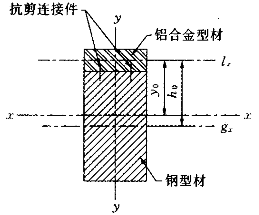
Click the steel structure design – official account above to pay attention to how to calculate the steel aluminum composite section members that are common in our curtain wall structure? Generally, there are two types of composite sections – composite composite sections (Figure a) and composite composite sections (Figure b).

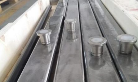
Stacked composite cross-section, with steel profiles covered by aluminum profiles, only nested and not connected, ignoring the friction between steel and aluminum, and coordinating displacement during bending; Composite composite section, with shear connectors between steel and aluminum profiles, can work completely or partially according to the assumption of a flat section when subjected to bending (determined by the strength and spacing of the shear connectors).

There are literature materials (Gong Qinhua, Li Shuo, “Design of Steel Aluminum Composite Section Members,” Steel Structures, 2003 (1)) that derive formulas from material mechanics methods to solve this calculation problem.

The formula for composite cross-section is derived as follows: For composite cross-section, the paper assumes a completely flat cross-section and converts the area of aluminum and steel profiles based on the ratio of elastic modulus, and then calculates them as composite cross-section.
However, in reality, it may not be applicable for situations where there are few shear connectors (in extreme cases, they are set at both ends and in the middle of the component), and there may be errors.
Because at this point, it does not fully meet the requirements of the assumption that the components in material mechanics meet the plane section assumption everywhere.
Hand calculation may not be accurate yet, and many people are afraid at first glance.
What should I do? In fact, considering the current calculation methods, it is entirely possible to solve the stress calculation of steel aluminum composite cross-section components through software modeling and direct calculation.
Steel and aluminum profiles are modeled based on beam elements and simply supported components, and divided into enough beam elements (the more accurate the more).
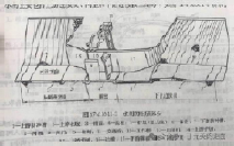
For laminated composite cross-section components – consider the forced displacement coordination condition based on the distributed chain members (with sufficient stiffness and hinged ends), as shown in the following figure.
For composite cross-section components – according to the actual distribution of shear connectors, rigid rods can be used to simulate (see the figure below).
The length of the rigid rod in the model is a bit particular, and the normal distance between the centroids of aluminum profiles and steel profiles should be (if the centroids overlap, a very short length can be used to approximate the simulation).
Of course, some programs have node forced displacement functions (such as master-slave nodes in MidasGen), which makes modeling more convenient.
Simply use master-slave nodes at the shear connectors to force the displacement of the beam nodes of the steel aluminum profile components to be consistent.
Welcome to the discussion section Source: From steel structures to prefabricated steel structure buildings, author: Niu Biren.
If there is any infringement, please contact us
.


