Click the blue “bridge magazine” above to pay attention to our efforts to improve the construction technology of highway concrete bridges and promote the high-quality development of highway construction, The Ministry of transport issued the new version of code for design of highway reinforced concrete and prestressed concrete bridges and culverts (jtg3362-2018) on July 16, 2018.

The application guide of code for design of highway reinforced concrete and prestressed concrete bridges and culverts published in September 2018 Further deepen the understanding and understanding of the new norms by clarifying the mechanism.

The new specifications and guidelines add a number of provisions on the design method of prefabricated bridges with prefabricated components, the structural details of precast segment joints, especially the external prestress technology closely related to them.

Combined with the relevant scientific research of the new code participated by the Bridge Engineering Department of Tongji University and the research practice of bridge prefabrication and assembly technology in recent 20 years, this paper further discusses its theoretical improvement and future development.

Precast segmental box girder bridge and rapid construction prefabricated bridge (ABC) with the rapid urbanization in China, the accelerated bridge construction (ABC) is being actively promoted at the industry level.

In fact, the construction concept of ABC bridge originates from the bridge construction in France.

E.

freyssinet adopts longitudinal precast beam segments (1945) and matching joints (1952).

J.

Muller (1979) built two long bridges in Florida In the design of (LongKey and sevenmile), prefabrication is combined with modern mechanical technology, and great progress has been made in technology.

Since then, segmental precast assembled prestressed concrete bridges have been widely used all over the world, such as mid Bay and garcon point sea crossing bridges in the United States (1990), inner ring line in Seoul, Korea (1996), mana high-speed viaduct in Bangkok (2000) et al.

Figure 1 Schematic diagram of fully prefabricated bridges.

Precast Segmental Bridges in China were only sporadically used before the 21st century.

Until the 21st century, precast segmental construction methods and external prestress technology have received more and more attention and affirmation in China.
Shanghai Liuhe Bridge (2001) adopted the construction method of external prestressed precast segments span by span, and used the upward bridge erecting machine for the first time in domestic highway bridges.
Subsequently, this technology was also used in the design of Shanghai humin line phase II project (2003).
The deep-water section of Sutong Yangtze River Highway Bridge has a span of 75m In (2003), the precast segmental cantilever assembly construction method was adopted, as shown in Figure 2.
This bridge is the first bridge in China to adopt precast segmental construction on a large scale.
Later, this construction method was adopted in the approach bridges of many river crossing bridges in China.
Figure 2 the stress essence of precast segmental bridge in the deep-water section of Sutong Bridge.
The stress essence of precast segmental bridge in the bridge structure of precast segmental construction, It can be regarded as a reinforced concrete structure inserted with several plain concrete sections, That is, the reinforced concrete section with continuous longitudinal ordinary reinforcement (section R) and the plain concrete section with disconnected longitudinal ordinary reinforcement (Section C, i.e.
joint), as shown in Figure 3.
Figure 3 Schematic diagram of the essence of beam joint in Section 3 (Section C) is the characteristic and weakness of Precast Segmental Bridges.
Although there are many engineering examples of bridges constructed with precast segments in the world, many international mainstream codes have not reflected up to now because the longitudinal reinforcement is completely cut off at the joint and the joint itself and its impact on the stress of the structure are very complex (Section C) is actually just mortar.
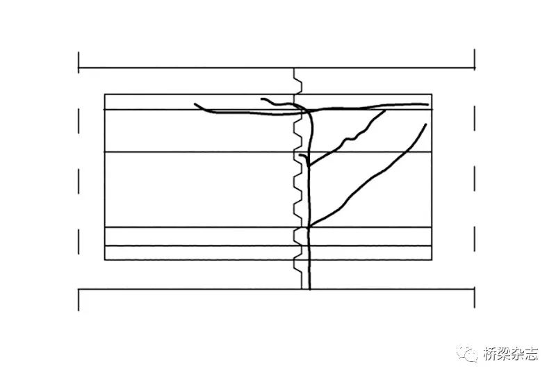
A large number of research results show that the crack development of precast segmental structure is basically near the joint, as shown in Figure 4.
In fact, the joint is like a preset crack position, as shown in Figure 5.
Its stress condition has been separated from the cornerstone of section method in structural design – all sections meet the plane assumption.
Figure 4 crack development near the joint Figure 5 crack Since the advent of segmental construction method, a large number of research and experiments have been carried out at home and abroad to study its mechanical performance.
Two methods are generally used in theoretical research.
The first is the structural method, that is, the whole process elastic-plastic finite element analysis method is adopted, but there are more studies on flexural performance and less studies on shear performance.
The main reason is that shear reinforcement itself is a difficult problem in the field of concrete structure, and there is no fully formed consensus method in the world.
The second is to adopt the traditional section method, which is a simplification coordinated with the standard method and is representative.
At present, the only one is the “guiding code for design and construction of segmental concrete bridges” issued by the American Association of interstate highway and transportation workers (AASHTO).
It divides the segment joints into two types, that is, the wet joints and glue joints between precast segments are called class a joints, and the dry joints between precast segments are called class B joints.
The following table 1 shows the bending reduction coefficient and shear reduction coefficient of AASHTO standard for segmental construction concrete structures with different prestressed reinforcement forms and different joint types.
The coefficient with 0.05 as the extreme difference in the table is empirical, but its advantage is that the section method adopted in the current specification can be directly adopted.
Longitudinal ordinary reinforcement needs continuous precast segmental construction of span joints.
The structural bearing capacity of the bridge is simplified by multiplying the coefficient by the section method.
Although it can be coordinated with the specifications, it can be seen from Figure 5 that its basis is not sufficient.
The elastic-plastic finite element method or test method considering the whole process, including internal force redistribution, is inconsistent with the section method adopted in the code, that is, its safety is different from the section method.
At the same time, most of its research methods focus on the bending problem.
Because there is no unified understanding of the shear capacity of concrete beams, the shear problem of segmental beams is more complex.
Table 2 is the design diagram of shear reinforcement in the world’s main codes.
(1) Only vertical stirrups are currently adopted by ACI of the United States and GB and JTG codes of China, but the value of concrete shear contribution is very different.
ACI of the United States only considers the load when the first bending shear or web shear crack occurs in concrete as concrete resistance; while the concrete resistance in Chinese codes is the failure load of beams without web reinforcement.
Therefore, the concrete contribution in Chinese codes is too large, resulting in The problem is that there are few shear reinforcement, and once the web cracks, the shear originally borne by the concrete is transferred to the reinforcement, which is easy to lead to the yield of the shear reinforcement, thus damaging the stress transfer path in the structure.
In engineering practice, it will cause wide inclined cracks, and the continuous downward deflection of prestressed concrete bridges due to the reduction of beam shear stiffness.
(2) Stirrups + main longitudinal bars at upper and lower edges are currently adopted in American AASHTO and European codes (the European Code also adopts the variable angle truss model without considering the contribution of concrete).
The vertical component of the oblique principal tensile stress is borne by the stirrup, the horizontal component continues to extend to the upper and lower edges with the development of the oblique crack, and finally is borne by the main longitudinal reinforcement at the upper and lower edges to form a shear resistant structure.
Its root is the truss model, which establishes the balance equation of the structure.
Therefore, in reinforced concrete In the structure, in addition to meeting the needs of bending resistance, the main longitudinal reinforcement also needs to consider the stress increment caused by shear.
This is a kind of “mechanism” balance, that is, the main reinforcement at the upper and lower edges can bear the horizontal components that continue to develop and extend upward and downward due to the inclined cracks.
These horizontal components are finally borne by the main longitudinal reinforcement at the upper and lower edges, so as to “support” the overall structure without causing shear collapse.
However, the problem is that the width of oblique crack can not be controlled, and this is a “mechanism” that can move wrongly along the oblique direction..


